Wednesday, July 22, 2020

"Swirls" — An Introduction to ENCs, and Why We Like Them

As you may know, at the end of 2024 NOAA will have completed the demise of all paper charts and the associated RNC echarts. We will all be using ENC by then, both in the echart format and in the new printed ENC format, called NOAA Custom Charts, NCC.

With that in mind, whenever we see a charting question arise in class that brings to mind the use of ENC, we jump on it,  and this is such an example.

The latest version of paper chart 18465, Eastern Strait of Juan de Fuca,  has on it a notation "swirls" near 48º 12.3'N, 123º 16.2'W. Following standard chart practice, you would turn to Chart No. 1 to learn what this means, but you would not find the word "swirls" in that booklet, which we can confirm with a search of the PDF version.  This is not a new chart notation on this chart. It was there in the 90s and likewise in the 90s it was also not in Chart No. 1.

We will be right if we guess this is related to spinning water or eddies of some form, but we still like all symbols and abbreviations on the chart to be well defined—as indeed most are; this is an anomaly.

In the age of ENCs, however, we have another way to see what this might mean. We start by looking at the same spot with both the latest ENC and latest RNC as shown below.
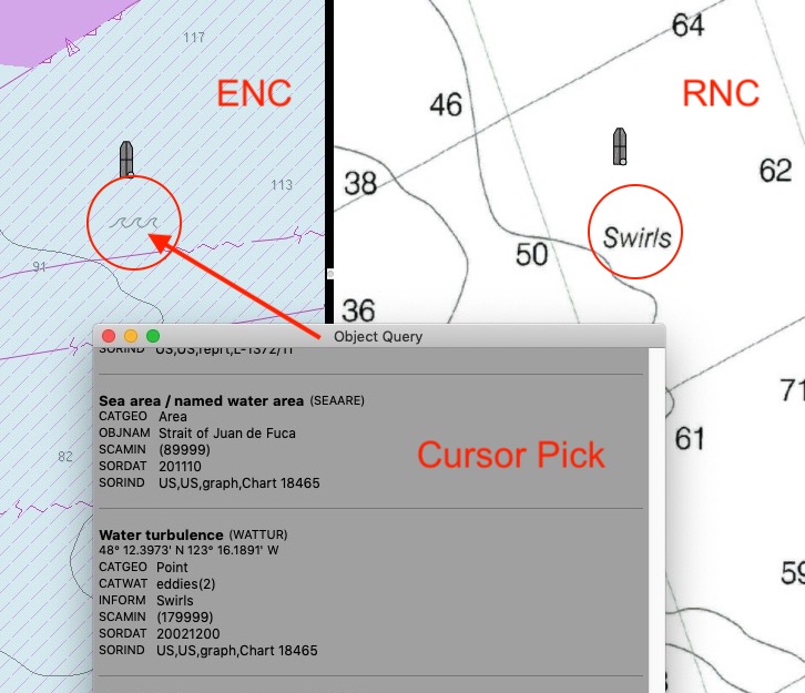

Figure 1

This view is from OpenCPN with the dual screen option. ENC on the left and RNC on the right set to the same scale, 1:21,300. (You can view the same thing in qtVlm, switching between vector and raster.)  Also shown is what ENCs call a "cursor pick," meaning I click the object (wave icon in this case) and up pops a list of the charted objects at that point, along with their individual attributes. We get nothing, of course, when we click any point on the RNC, as that is just a static image of the paper chart. In contrast, every point on the ENC brings up at least one object, and usually many.

Here we scroll the list to show just two objects, SEAARE (sea area), which is the Strait of Juan de Fuca, plus the subject at hand, the object WATTUR (water turbulence). The wave icon on the chart is the symbol for WATTUR. it is defined as: "The disturbance of water caused by the interaction of any combination of waves, currents, tidal streams, wind, shoal patches and obstructions."

Every object on an ENC has a 6-letter abbreviation, and although the official IHO display standard (S-52) discourages the use of abbreviations in favor of the plain-language names, our own experience is the abbreviations can be useful for communication, so we are glad to see OpenCPN include them. Here is the presentation of this object in an online S-57 object catalog from Russia (S-57.com). There is also an excellent US-Canadian version from Caris, but its URL is not as easy to remember!


Figure 2

Each object has in turn a set of attributes that describe the object, which are outlined above.  These attributes also have a 6-letter abbreviation, which could be confusing, but in practice once we get used to using ENC and the related terminology, it is not an issue.

Type A attributes are actual characteristics of the object; type B are relevant to the use of the object data; and type C relate to the sources of the data. Crossed out ones are no longer used. Underlined are mandatory for every example of that object.

We come back to the other information on this screen, but now just note that this object has attributes:

CATWAT (category of the water turbulence), 

OBJNAM (name of the object), such as famous "Liddel Eddy" in the Orkneys,

SCAMIN  (the minimum scale that shows the object on an ENC), and the last one we cover here,

INFORM, which is a text description of the object, described as:  "The textual information could be, for example, a list, a table or a text. This attribute should be used, for example, to hold the information that is shown on paper charts by cautionary and explanatory notes." This attribute is the key to the present discussion.

Object attributes are often categories, such as CATWAT, listed above, which can take on the values, which are defined in either of the two online object catalogs mentioned:


Figure 3

These categories are defined as:
1. breaker: a wave breaking on the shore, over a reef, etc. Breakers may be roughly classified into three kinds, although the categories may overlap: spilling breakers break gradually over a considerable distance; plunging breakers tend to curl over and break with a crash; and surging breakers peak up, but then instead of spilling or plunging they surge up on the beach face. The French word 'brisant' is also used for the obstacle causing the breaking of the wave. (IHO Dictionary, S-32, 5th Edition, 540) 
2. eddies: circular movements of water usually formed where currents pass obstructions, between two adjacent currents flowing counter to each other, or along the edge of a permanent current. (IHO Dictionary, S-32, 5th Edition, 1560)
 3. overfalls: short, breaking waves occurring when a strong current passes over a shoal or other submarine obstruction or meets a contrary current or wind. (IHO Dictionary, S-32, 5th Edition, 3631)
4. tide rips: small waves formed on the surface of water by the meeting of opposing tidal currents or by a tidal current crossing an irregular bottom. (IHO Dictionary, S-32, 5th Edition, 5494)
5. bombora: a wave that forms over a submerged offshore reef or rock, sometimes (in very calm weather or at high tide) nearly swelling but in other conditions breaking heavily and producing a dangerous stretch of broken water; the reef or rock itself. Also called bumbora or bomborah. (Australian National Dictionary)
Referring back to Figure 1, we see that the cursor pick reported CATWAT = 2 for eddies, but then we see the interesting note that INFORM includes the single word "swirls," which is indeed intended to link this ENC symbol to what is on the paper chart.

I can't really say "in short" after all that, but we can get a glimpse now of how an ENC can provide more information about charted objects.  On the paper chart, we see the word "swirls" only, and that word is not in the main reference Chart No. 1. In passing, it is also not in the more fundamental IHO charting standard called S-4 (Regulations of the IHO for International Charts). Nor is it in the IHO Dictionary, S-32.

In this case, that one word is all we get in INFORM, but it could hold up to 300 characters of information and tell us more, such as what stage of the tide it is most pronounced, and so on. The attribute TXTDSC (text description), will generally include any notes from the US Coast Pilot about this object. This is the way that ENC puts chart notes near or on the objects they describe.

You could say that this is a lot of work to learn that swirls means eddies in this case, which we might have guessed, but it could also have been tide rips, but that is not really the point here. Here I just want to use this as an introduction to how ENC data are presented as we transition into all ENC in a couple years.

With that in mind, let's look at one other detail. In Figure 3 from an online object catalog we see that in this presentation of the attribute CATWAT we are also given the corresponding paper chart object locators. "INT 1" refers to the US and other national Chart No. 1 documents; the S-4 numbers refer to the IHO S-4 document linked above.  The S-4 presentation is shown below,  followed by the Chart 1 presentations.


Figure  4.  Chart symbols according to S-4


Figure  5.  Chart symbols according to US Chart No. 1

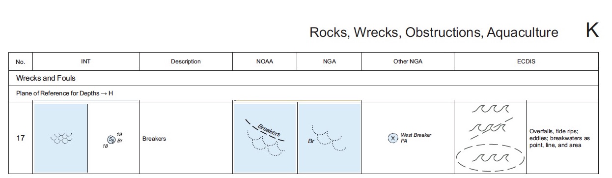
This is just another way we can correlate ENC symbols (new to some mariners) with the paper chart symbolism we are accustomed to.


Sunday, July 19, 2020

A Sight Reduction of the Sun

This is an outline of the process using our Starpath Work Form 104. The exercise is from our Online Cel Nav Course, Quiz 3 Question 16 (CN03-0016). Following the outline here is a link to a video with more discussion.

Here is the exercise:
For this exercise we use the 1978 Almanac data from our textbook, but we have to use a full set of Increments and Corrections and we need a full set of Pub 249 vol 2.

Forms, Sight Reduction Tables, Increments and Corrections, and indeed even the Almanac data can be found at starpath.com/celnavbook.

Below is the filled out form, which is the answer to the question, followed by notes on where each of the values come from. We ask our students to follow through on this example to understand each step following the instructions in Chapter 3 of the textbook, which covers each Box in the form.  We also have a book (Starpath Celestial Navigation Work Forms) that explains our forms step by step, with several examples. It is effectively a short course on cel nav.

Below is just a very short discussion, not intended to replace what is in the textbook.


Box 1 is the sight data, all given for any sight.

Box 2 and 3 are the look ups for the GP of the sun at sight time. first the whole hours part from the daily pages of the Almanac, then the minutes and seconds correction from the Increments and corrections tables.


Increments and corrections for Box 3.


Add up hour and min-sec parts to get GHA. Then choose the assumed position (AP = a-Lat, a-Lon).  Round the DR-Lat to nearest whole degree to get a-Lat, which is 38º N.  Then choose the a-Lon to be the closest Lon to the DR-Lon that has the same minutes as the GHA. In this case a-Lon = 1º 55.6'W.  We cannot use 45º 55.6' because that one is more than 30' from the DR Lon. (We have extended practice with choosing the a-Lon in Section 11.13 in the textbook.)

With these values we can then find final LHA = GHA – a-Lon, and fill Box 4 that we need for the sight reduction tables and then turn to Pub 249, Vol 2 for Lat 38, Same Name, Dec = 19, LHA = 317. which we find on the page below.


Now we get the correction to Hc based on d value and Dec minutes.  Then we add this correction to tabulated Hc to get final Hc, completing Box 5.  Hc = 48º 34.2' 


Now we do the right side of the form to convert Hs to Ho, and then we compare Ho to Hc to get the a-value. Plus convert Z to Zn and we are done.

For the IC we use the rule "if it is on, we take it off," so this is -1.0'. We find the dip and altitude corrections from the Nautical Almanac page shown below:


To find the correct altitude correction, first note the date.  We are July which is between April and Sept. Then check we are Lower Limb, then go down the column to find Ha.  We always want the center of the body, so LL means this is a + correction; UL this will be a – correction.

Now use the rules on the form and on every sight reduction tables page that tells us how to convert from Z to Zn, as in previous image. 

Then subtract Ho and Hc, smaller from larger and that is the a-value and take the label next to the largest. In this case our LOP is a = 11.6A from 105T.  We plot this from the AP 38N, 44 55.6W.

You can always check your work with Celestial Tools, SR & Fix function as shown below:


This shows all the values you should get on intermediate steps. Note that Celestial Tools rounds dec and dec corrections to whole minutes, which is the official Pub 249 procedure. We get slightly different values as we interpolated the d correction. (In this case we end up about 0.2' more accurate than had we rounded. In other cases it could be as much as twice that better, but indeed in a few cases, this rounding will make things worse by a couple tenths.)


Friday, July 17, 2020

A Sight Reduction of Jupiter

Here is the exercise we will solve. It is from our Cel Nav Course, Quiz 8, #19 (CN08-0019).  This is an outline of the solution. At the end is a  28 min video discussing each of the steps. You can click each of the images below for a higher res view.


Resources used can  be found at starpath.com/celnavbook


Here is the filled out work form. Following that are pages from the Almanac and Pub 249 Sight Reduction tables used. You might print out this completed form and follow through the steps below.

We also have a book (Starpath Celestial Navigation Work Forms) that explains our forms step by step with several examples. It is effectively a short course on cel nav.


Box 1 is all from the given sight data in the question. 

(For this exercise we are using the DR position given at 0300, whereas the actual sight was at 0410. In principle it would be best to DR to the time of the sight, and use that value to choose the assumed position. This is addressed at the end of the article.)

Box 2 is from daily pages of the Nautical almanac


Box 3 we get from the Increments and Corrections pages. 


Now that we know GHA we can choose the assumed position (AP = a-Lat, a-Lon).  Round the DR-Lat to nearest whole degree to get a-Lat, which is 30º S.  Then choose the a-Lon to be the closest Lon to the DR-Lon that has the same minutes as the GHA. In this case a-Lon = 115º 7.4' W. 

With these values we can then find final LHA = GHA – a-Lon, and fill Box 4 that we need for the sight reduction tables and then turn to Pub 249, Vol 2 for Lat 30, Contrary Name, Dec = 18, LHA = 322. which we find on the page below.


Write these values for Hc, d and Z into Box 5. Now we need to look up the d correction

Our d value is -52, our dec minutes are 43.8. We note that dec min 43 has correction 37 and dec min 44 has correction 38, so we can interpolate by eye to get our correction as 37.8, which is minus and this goes into Box 5. And we find the final value of Hc = 34º 18.2', which we copy to the right side of the form, following the arrows.

Also figure Zn from Z, using the rules on the work form. These same rules appear on every page of the sight reduction tables as well. Here we are S Lat with LHA > 180, so Zn = 180 - Z. Figure that and add to the form.

Now we convert Hs to Ho on the right side of the form.

We get dip and altitude correction from the Almanac page below:


Add these to the form and sum up to get Ho. 

Note that the two closest planets Venus and Mars can have an additional alt correction, which will be in the middle column. These are dependent on the year. Jupiter and Saturn do not have these.

Now subtract Hc and Ho, smaller from larger to get the a-value, and label it with the letter next to the larger of the two... or use the jingle "Calculated greater away" or "If
Ho is Mo it is To."

So the answer the question is: (a) Assumed position is 30º S, 115º 7.4' W and (b) the LOP is a = 0.9'A from 033.
______________

Two last thoughts to wrap up this exercise:

(1) The DR position given was earlier than the sight time, so in principle we should DR from 0300 to 0411 to find the right DR to use for choosing the AP.  This plot is shown below:


We see that the new DR does not affect our choice of AP. This step, however, should be checked for all exercises like this one.

(2) We have a useful training tool in Stan Klein's Celestial Tools.  The option called "SR Methods & Fix."  This unique function shows what you should get at each intermediate step in a sight reduction depending on which method you select. Here we chose Pub 249, v2 or v3. We see below that he computes what we see in the form.  Check out this neat tool as a way to verify your work... especially as you move on to using the NAO tables (he calls them NASR) or or Pub 229.


____________

To see a video of the above notes with more discussion see below (caution, it is 28 min long!)


Sunday, June 7, 2020

Introduction to Vessel Running Lights (Navigation Lights)

Navigation lights help identify vessel type and its direction of motion.  The required lights are specified in the Navigation Rules, Part C, Rules 20 to 31.  Power vessels in Rule 23 and sailing vessels in Rule 25 are the two classes we focus on here. These two basic vessel classes have simple rules.  Other vessel classes (towing, fishing, restricted motion, etc) are covered in other Rules. Rules for towing vessels are complex.  An important part of these rules is  included in Rule 20b, namely that no other lights than those specified by the rules should be shown if they could possibly interfere with the identification of the required lights.

The lights are required (must be shown) from sunset to sunrise, but may be shown any time deemed appropriate. Note that automobile lights are required from evening twilight to morning twilight, which is a longer period, but less precisely defined.

For now we look at the three basic nav lights categories: sidelights (red and green), masthead lights (white), and sternlight  (white). These are defined in Rule 23a. These rules establish the terminology as well: sternlight and sidelight are written as one word.

Sidelights are seen from dead ahead to 22.5º abaft the beam. Sternlight is shown in the aft gap between those two, and the  masthead lights are seen from everywhere except the stern sector, ie masthead lights and sidelights are seen from the same sectors.

The seemingly strange choice of 22.5º is a historic accident as this equals two points on the compass and the original Rules from the 1800s were written in terms of compass points. See our note on boxing the compass.


For now we consider only power driven vessels (PDV) and sailing vessels (SV). Note that a sailboat is only an SV when it is actually sailing, no engine engaged, else it is a PDV. This fact applies not just to lights but to all aspects of the rules. A sailboat under power is a powerboat.

We consider PDV in only two categories for now: less than 50 m (164 ft), and 50 m or more in length.


Larger vessels require two masthead lights, the forward one lower than the aft one. Thus seeing them on the horizon we know which way the vessel is headed. The above and below pics are from the USCG Navigation Rules Handbook.  There is also a printed edition.


For our Radar Course quizzes, we have to determine which lights we see based on the relative motion track of the vessel on the radar screen—but a first step in that analysis is knowing what the lights look like from various perspectives in plain sight.

Referring back to the first figure, from anywhere in the red sector you would see only one red light and one or two white masthead lights; same from the green sector, one green and one or two whites depending on the size of the vessel.

In the aft sector, you would  see only one white light, the sternlight.  A 15 ft runabout and the Queen Mary look the same from astern.

From dead ahead you would see red and green sidelights. In this case "dead ahead"—as determined by seeing the other vessel's sidelights—is tied to the technical specs of the lights. According to the Rules, they must fade to zero intensity within 3º of dead ahead. In other words, in principle you should never see green from left of the bow, but to account for technical limitations, you should never see green at all beyond 3º to the left of the bow. 

The borders at the aft end of the range are ± 5º, meaning the specified intensity (visual range) must apply to at least within 5º of the aft limit, and then must attenuate to 0 by 5º beyond that. See:

COLREGS Annex I— Positioning and Technical Details of Lights and Shapes,
Section 9. Horizontal sectors
(a) (i) In the forward direction, sidelights as fitted on the vessel shall show the minimum required intensities. The intensities shall decrease to reach practical cut-off between 1 degree and 3 degrees outside the prescribed sectors.
(ii) For sternlights and masthead lights and at 22.5 degrees abaft the beam for sidelights, the minimum required intensities shall be maintained over the arc of the horizon up to 5 degrees within the limits of the sectors prescribed in Rule 21. From 5 degrees within the prescribed sectors the intensity may decrease by 50 percent up to the prescribed limits; it shall decrease steadily to reach practical cut-off at not more than 5 degrees outside the prescribed sectors.
This means that a head-on course could vary from reciprocal by as much as 6º and in practice even more due to improper shades on the lights and the yawing about of the headings. Understanding the head-on encounter is crucial to safe navigation. Not maneuvering before you are certain of the situation is also crucial. 

The aft boundary (two points abaft the beam) that separates the crossing and overtaking courses as determined by lights has an uncertainty of ± 5º.  We can often determine relative courses to well within this accuracy by solving the relative motion diagram on our radar screen. 

We can also learn the other vessel's course (COG) from its AIS signal if available. Vessels with a heading sensor programmed into the AIS will also tell us their heading, which is what determines the lights we should see.  With no current or leeway, the heading and COG would be the same.

(In the formative days of the Rules, the sidelights were specified to extend 4º across the bow, but that proved dangerous and was ended in the 1890s. Side lights was two words in those days.)

Masthead lights can be seen from farther off than sidelights.  Below are the required ranges given in Rule 22, for the three lights we consider here:

(a) In vessels of 50 meters or more in length:
  • (i) a masthead light, 6 miles;
  • (ii) a sidelight, 3 miles;
  • (iii) a sternlight, 3 miles;

(b) In vessels of 12 meters or more in length but less than 50 meters in length;
  • (i) a masthead light, 5 miles; except that where the length of the vessel is less than 20
  • meters, 3 miles;
  • (ii) a sidelight, 2 miles;
  • (iii) a sternlight, 2 miles;

(c) In vessels of less than 12 meters (39.4 ft) in length:
  • (i) a masthead light, 2 miles;
  • (ii) a sidelight, 1 miles;
  • (iii) a sternlight, 2 miles;

It is clear why we can see a ship from farther off than a smaller vessel. The lights are higher and indeed brighter. In all cases, we see the masthead lights before the sidelights.

Below are samples of how the aspect of the lights tell us how the vessel is moving.


These two pictures are from our book Fundamentals of Kayak Navigation. All vessels care about understanding navigation lights.

The mariner at location A sees a red turn into red and green, and then into green alone, as the vessel turns toward them and then white as they passed. Vessel B sees a red light the whole time, except possibly at the very last location where it would go white. Study this figure to be sure both views are clear.


Masthead lights on a ship are often referred to as its "range lights,"  because we can think of them as a navigational range, and use that concept to decide where we are relative to that range. When navigating in the vicinity of a charted navigational range, when the two lights are lined up from our perspective (the more inland one is always higher), we know we are precisely on the charted line that the two lights define. In the case of a vessel, this means we are looking directly at its bow.  Recall we do not see masthead lights astern; only on the sides and ahead.

As the vessel turns toward us at the top of the pic, we see the range lights "closing"; as it turns away from us, we see the range lights "opening."  This is common terminology in nighttime navigation:  Are the masthead lights opening or closing?  When the two lights are lined up, one above the other, the ship is headed straight toward us.  We often can see these lights with binoculars and identify its heading long before we see its sidelights.

Sailboat lights are summarized in the figure below


When sailing, there are sidelights and a sternlight, but no masthead light. Under 20m (65.6 ft) all underway sailing lights can be in a combined unit at the masthead—but vessels choosing that option must also have deck level sidelights because the tricolor is not legal under power. Thus a sailing vessel can likely have both masthead sidelights and deck side lights but these cannot be run at the same time. There is a rarely used optional all-round red and green masthead light for when sailing.

Under power, sailboat lights are easy; they are same as  PDV of the same length.  The above figure is from our textbook Inland and Coastal Navigation.

As you study navigation lights, keep in mind the salient fact that every collision involves the violation of at least one of the Navigation Rules by both vessels. For collisions at night, illegal lights are almost guaranteed to buy you some fraction of the liability, even if they or you were not the primary cause of the collision.

Also it takes an effort to ensure that sailboat lights are legal. It is worth taking the time to view your boat at night from another boat at all aspects—or have a friend take a cellphone video. Sometimes sidelights on a bow can reflect from the bow pulpit or a sail on the bow and be seen in many directions. The light used to illuminate the masthead windvane (Windex) can often be seen as a white light, and so on.

A version of the Navigation Rules that is easy to search is our Pocket Navigation Rules Handbook. You can view it online and then save as a PDF and the cross links should work. Then mail it to yourself and open in your phone and save into the library of your favorite ebook reader.

Samples of running lights.


Vessel under sail is very simple. Sidelight or sternligbht.  If we see only a sidelight with no masthead, that is likely a sailboat undersail.


A sailboat sternlight, but we only know that because we can see the boat.  Seeing only the light, we do not know what kind of vessel it is... which in a sense does not matter if we are overtaking, we have to stay clear.


A ship's sternlight.


Cruise ships are mixed bag when it comes to lights.  The positive is you cannot miss them, they are a great smear of lights. The negative part is it is very difficult to see any of the official lights in the maze of other lights so it can be hard to tell which way they are going... if they are going at all.  They could be just drifting gambling casinos.

Here we can see the two sidelights as it turns left in front of us (red, red and green, and green), but note the illegal red light on the starboard side. It can be difficult to identify their masthead lights—but this is not a fair evaluation of that because we are so close.


A cleaner view of a ship's green sidelight and masthead lights. Many ships that do show distracting lighting when near port, do not have these extra lights on at sea. This is true of cargo and tanker vessels, not cruise ships.


Here is a case of many distracting lights but the mastheads (range lights) are still clear, as is the port sidelight.


This screencap is from—believe it or not—a video about using the proper lights. It is recorded from a speaker on the vessel we see here, filmed by another vessel following it around. This is an example mentioned above of unwanted reflections of your sidelights... the strange part is they could watch this and not edit this out.