Wednesday, December 13, 2023

How to Remember the Equation of Time


On Valentine’s Day, February 14, the sun is late on the meridian by 14 minutes (LAN at 1214); three months later, it is early by 4 minutes (LAN at 1156). On Halloween, October 31, the sun is early on the meridian by 16 minutes (LAN at 1144); three months earlier, it is late by 6 minutes (LAN at 1206).

These four dates mark the turning points in the Equation of Time. You can assume that the values at the turning points remain constant for two weeks on either side of the turn, as shown in Figure 12-7. Between these dates, assume the variation is proportional to the date.


There is some symmetry to this prescription, which may help you remember it:

14 late three months later goes to 4 early

16 early three months earlier goes to 6 late

but I admit it is no catchy jingle. Knowing the general shape of the curve and the form of the prescription, however, has been enough to help me remember it for some years now. It also helps to have been late sometimes on Valentine’s Day! An example of its use when interpolation is required is shown in Figure 12-7.

The accuracy of the prescription is shown in Figure 12-8. It is generally accurate to within a minute or so, which means that longitude figured from it will generally be accurate to within 15′ or so.


This process for figuring the Equation of Time may appear involved at first, but if you work out a few examples and check yourself with the almanac, it should fall into place. If you are going to memorize something that could be of great value, this is it. When you know this and have an accurate watch, you will always be able to find your longitude; you don’t need anything else. With this point in mind, it is worth the trouble to learn it.

Also remember that the LAN method tells you what your longitude was at LAN, even though it may have taken all day to find it. To figure your present longitude, you must dead reckon from LAN to the present. Procedures for converting between distance intervals and longitude intervals are covered in the Keeping Track of Longitude section below.

For completeness, we should add that, strictly speaking, this method assumes your latitude does not change much between the morning and afternoon sights used to find the time of LAN. A latitude change distorts the path of the sun so that the time halfway between equal sun heights is no longer precisely equal to LAN. Consider an extreme example of LAN determined from sunrise and sunset when these times are changing by 4 minutes per 1° of latitude (above latitude 44° near the solstices). If you sail due south 2° between sunrise and sunset, the sunset time will be wrong by 8 minutes, which makes the halfway time of LAN wrong by 4 minutes. The longitude error would be 60′, or 1°. But it is only a rare situation like this that would lead to so large an error. It is not easy to correct for this when using low sights to determine the time of LAN. For emergency longitude, you can overlook this problem.

In preparing for emergency navigation before a long voyage, it is clearly useful to know the Equation of Time. Generally, it will change little during a typical ocean passage. Preparing for emergency longitude calculations from the sun involves the same sort of memorization required for emergency latitude calculations. For example, departing on a planned thirty-day passage starting on July 1, you might remember that the sun’s declination varies from N 23° 0′ to N 18° 17′ and the time of LAN at Greenwich varies from 1204 to 1206. Then, knowing the emergency prescriptions for figuring latitude and longitude, you can derive accurate values for any date during this period.

This article is taken from Emergency Navigation by David Burch

Monday, December 4, 2023

Great Circle Distance — The Three Options

The great circle (GC) route is the shortest distance between two points on the globe, so we must always keep it in mind when planning an ocean crossing, even if we do not end up following that route. 

The GC route is defined by cutting the earth with a plane that goes through the departure (A), the destination (B),  and the center of the earth (C). That plane cuts the earth in half, and the points A and B lie along a circle (a great circle) whose circumference is the circumference of the earth, and the track along that line from A to B is called the great circle route.  If the plane does not go through the center of the earth, you also get a circle where it intersects the earth, but its circumference will be smaller than that of a great circle.


Distance along a great circle is measured  in nautical miles, which is a unit that was invented for just this purpose. Namely, the full great circle spans 360º, and each degree is 60', so a nautical mile (nmi) is defined as the length of 1 arc minute (1') along the circumference of a great circle of the earth. 

This is very convenient for navigation if we consider the great circle between the north pole, earth center, and south pole, which is a meridian of longitude. Arc minutes along this great circle are minutes of latitude.  Thus a navigator knows immediately if they are to sail from Cape Flattery, WA at about Lat 48 N to San Francisco at about Lat 38 N, they must go 10º of Lat or 600 nmi. Every 1' of Lat = 1 nmi.

There are other implications of this definition that are integrally related to the topic at hand.  For one, this assumes the earth is a sphere... which is not too radical an idea, having been known — or believed to be true — by every educated person on earth except Christopher Columbus for over a thousand years

As it turns out, the earth is not a perfect sphere, it is squashed a bit at the poles, as we might slightly compress a beach ball into more of a doorknob shape. Consequently a nautical mile cannot be simply defined as 1' of Lat, because the length of 1' of Lat changes slightly with latitude on this non-spherical shape. That simple definition is reserved for the less precise term sea mile, which is defined as 1' of Lat at a constant Lon. But nautical mile is the official international unit of global navigation so it has to have a definition, and that was given to it 1929: 1 nmi = 1852 meters, exactly.

That definition then tells us what we mean by spherical earth, based on the geometry of a circle. Namely, the circumference (c) of a circle = 2 𝜋 x radius (r) of the circle. Thus we have for spherical earth, c = 2 𝜋 r = 360 x 60 x 1.852 km, or solving for r:

r (spherical earth) = 360 x 60 x 1.852 /(2 x 3.141) = 6,367.9 km.

Thus we are at the first of three types of great circle distance computation, which is assume the earth is spherical with a radius of 6,367.9 km, which makes 1' on the circle = 1 nmi and we can use spherical trigonometry to compute the great circle distance (d) between point 1 and point 2, namely:

Cos(d) = Sin(Lat1) x Sin(Lat2) + Cos(Lat1) x Cos(Lat2) x Cos(Lon2 – Lon1).

This formula can be solved with an inexpensive trig calculator, and indeed this is the solution we would see in many calculators or apps, especially those that are largely celestial navigation oriented, because cel nav assumes the earth is a sphere as defined above.

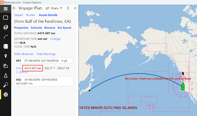
If we use this method to compute the GC distance between San Francisco (37.8N, 122.8W) and Tokyo (34.8N, 139.8E) we would get 4,473.61 nmi.

But it is not just cel nav apps that use this equation. The Bowditch computations also assume this same 1' = 1 nmi spherical earth, and present the same value.

Besides cel nav focused apps, some chart navigation apps, officially referred to as electronic charting systems (ECS), also use this spherical earth solution, such as Rose Point's Coastal Explorer. We might call this traditional radius, the cel nav radius (6,367.9 km).


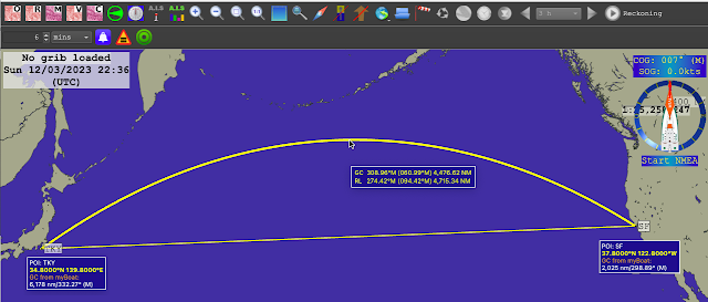
But if we open another popular ECS like qtVlm, and ask for the GC distance between these two points we get a different answer, 
namely 4,476.62 nmi. 


We see essentially the same answer in OpenCPN.


It is not just qtVlm and OpenCPN (two popular free ECS),  other computer or mobile nav apps might show this answer for these two points.

...that is, unless we are looking at a GPS chart plotter app or a handheld GPS unit with routing options, such as the Garmin GPSmap 78 shown below. 


In this case, we get a still different value of this same "great circle distance," namely 4,486.7 nmi. 

We also see this value in the ECS TimeZero.


In short, we have three values for the "great circle" distance between SF and TKY, and the one we get depends on how or who we ask. The differences in these example spans 13.1 nmi — and this, in an age where we pride ourselves with a GPS that gives our position accuracy to about a boat length or two (± 0.01 nmi).

Navigator's do not like inconsistent information, and will usually stop to figure out the source of the discrepancy. This note is intended to help with that.

The three values we noted were presented in increasing accuracy, which is tied to the shape of the earth that was used to compute the value. In most cases, these differences do not have a practical affect on navigation, but it is good to know if something is working right or not, and to understand what we see.

Type 1.  SF to TKY = 4,473.61 nmi. Spherical earth with 1' = 1 nmi. This solution is used in cel nav and other apps, as noted. Earth radius used is 6,367.9 km. The cel nav radius.

Type 2. SF to TKY = 4,476.62 nmi. This is what we would see in selected ECS that want to improve on the accuracy by using an improved earth radius. 

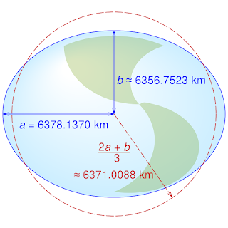
An improved earth shape is more of an oblate ellipsoid (doorknob), which can be approximated with a new spherical earth, but now using the average of the polar and equatorial radii, as shown. This improved method still computes the distance as a spherical earth, but uses this slightly smaller average radius of 6,371.0 km. This can be called the WGS84 average radius.


WGS84 earth dimensions. Keep in mind the scale. The equatorial bulge (7 km)  is just 0.1% of the radius; the depression of the poles (15 km), just 0.2%. The earth is actually pretty spherical.


Type 3.  SF to TKY = 4,486.7 nmi. Is in principle the most accurate solution as it uses not assume a spherical earth shape, but computes the distance along the surface of an oblate ellipsoid, the size and shape of which we get from the geodedic datum we have selected, such as WGS84. We will get this (Type 3) solution in most apps or hardware that lets us choose the horizontal datum, such as any GPS unit, hand-held or console chart plotter. This choice is actually an important thing to check in your GPS to be sure it matches your nautical charts; most should default to WGS84.


We also get this geodetic or ellipsoidal solution for "great circle" distances in several popular computer based ECS, such as TimeZero.


Google Earth will also give this value, but for other locations you may get different results as they may use different datums for different locations, which we do not seem to have control over. (The same is true, by the way, for the elevation data set or model it uses for different parts of the world. It is likely the best we can conveniently come by, but we will not know the details.)


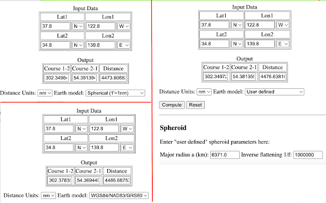
Numerical values of these distances can be checked online with the
Jack Williams calculators.


These values can be used to determine what type of computation your device is doing. Use Departure = (37.8, -122.8); Destination =  34.8, 139.8). 
Then check for the GC distance between them.

4473.6 means spherical earth using the cel nav radius (6,367.9 km)
4476.6 means spherical earth using the WGS84 average radius (6,371.0 km)
4486.7 means a WGS84 ellipsoidal computation

A consequence of a true ellipsoidal computation means a nominal, long-distance great circle estimated position depends on which way you are headed. Consider starting from the equator at 130 W and traveling 50º N versus 50º E. Sailing along the surface of a spherical earth, the distance you travel would be the same in both directions, namely 3,000 nmi. But sailing on the surface of an oblate ellipsoid, this is not the case. You have a smaller radius going toward the pole than you do going along the equator. Going north you sail 2,991.8 nmi but sailing east you go 3,005.4 nmi.


For completeness, let me add a 4th solution!  One that goes in the other direction: not striving for high precision, but looking for a solution that can be done with a plastic device that still works if soaking wet, after falling off the nav station and getting stomped on by numerous crew members' wet boots.

Great Circle Solutions with the 2102-D Star Finder


Tuesday, October 24, 2023

Reducing Station Pressure to Sea level pressure


The following is taken from The Barometer Handbook By David Burch. All references are to that text.


Recalling that the vertical rate of pressure change is always thousands of times higher than the horizontal rate that creates the wind and weather we care about, it is easy to see that observed pressures at various elevations must be carefully normalized to sea level if we are to learn about the true pressure pattern at hand.

In this section we outline how meteorologists determine sea level pressures from the reports they receive from varying elevations. We do not have call to do this ourselves very often, but the procedures are here if you care to. To be more precise, this is how meteorologists used to do it, based on  procedures  specified in detail in the Manual of Barometry (WBAN).  These procedures give some insight into the physical  factors that contribute to the reduction, but in practice today they use a much more empirical method, covered at the end of this section.

Step one is to clarify the concept of sea level pressure at, for example, a high plateau located inland, far from the sea—or even far from anywhere whose elevation might be near sea level. This is certainly an abstract concept, but one that is needed to normalize the observations.

The procedure is to imagine a large hole in the ground at the elevated station that reaches down to sea level. Then the question reduces to estimating what the pressure would be at the bottom of this hole based on the pressure we read at the elevated station level, along with the temperature and dew point of the air at the station level.

We know the weight of the air from the station level on up to the top of the atmosphere. That is just the station pressure we observe. So the problem reduces to figuring out how much the fictitious air column weighs in the fictitious hole.

An easy way to approximate the answer is to assume the air in the hole behaves exactly like the International Standard Atmosphere (ISA). Then we can just go to Table A2 and look up the answer. For example, consider being at an elevation of 1,200 feet above sea level. From Table A2 we see that this elevation corresponds to a pressure drop of 43.2 mb in the standard atmosphere. So if our actual station pressure were 985.5 mb, we would estimate that the pressure at sea level was 985.5 + 43.2 = 1028.7 mb.

This approximation assumes the air in the hole has exactly the average properties of the standard atmosphere. This is unlikely to be true, and we could even know this ahead of time by comparing the station pressure and temperature with the standard atmosphere values at our elevation. We can improve on this ISA approximation significantly, but it takes some number crunching to do so.

The weight of the air in the hole depends on the density of the air, which in turn depends on the average temperature of the air column as well as the moisture content—the ISA assumes dry air (relative humidity = 0%). For a better estimate of the weight of the air column, we need a better estimate of the average temperature of the air column. A complicating factor is the amount of water vapor in the air. This not only changes the density of the air directly, it also affects how the temperature changes with increasing elevation.

The standard way to simplify these calculations is to define the “virtual temperature” (Tv) of moist air  as the temperature that dry air must have in order to produce the same pressure and density the moist air has. The definition is illustrated in Figure A3-1.


We can then study the properties of a column of moist air as if it were dry air by replacing the average temperature with an average Tv. The formula for Tv depends on the station temperature, pressure, and dew point. In principle, each equation in Chapter 9 on altimetry that contains a T, should have that T replaced with Tv for the most accurate results. We will calculate this Tv in a moment, but first a more basic practical matter.

We will need a measurement of the station pressure if we are to find the sea level pressure. If you have actually measured the station pressure yourself, then you are done. That is the one you will use. But if you are testing this procedure of reducing station pressure to sea level pressure by analyzing data from another location, you still need the station pressure at that location, but you will soon learn that information may not be available. With the exception mentioned at the end of this section, station pressures are rarely reported. What they do, instead, is automatically reduce the station pressures to sea level pressures and report those. All airport reports, however, always compute the altimeter setting, discussed in Chapter 9. The reports are called “Metars,” derived from a French phrase meaning weather reports from airports.

Altimeter setting, by definition, depends only on the station pressure and elevation of the station, so we can unfold the altimeter setting (AS) to get the station pressure (Ps) we need from the equation:

Ps =[AS0.1903 - (1.313 x 10⁻⁵) x H]5.255,

where H is the station elevation in feet. This is the hypsometric equation with the temperature replaced with the ISA lapse rate. AS is given in inches of mercury, so Ps will be inches of mercury as well, but we can convert to mb as:

Ps (mb) = 33.864 x Ps (inches)

The above two equations are not from the WBAN procedures, but taken directly from NWS computer code. I apologize for the mixed units necessary if we use the exact equations presented in both methods.

 Once we have the station pressure, we can proceed with the WBAN procedure by computing the virtual temperature of the air. Start with finding the vapor pressure of the air (e) in mb from:

e = 6.11 x 10E

where e is in mb, 

E = 7.5 x Td/(237.7 + Td), 

and Td is the dew point of the station air in °C. Then we can find Tv in °K from:

Tv = (Ts + 273.15)/[1 - 0.379 x (e/Ps)]

where e and Ps are in mb, and Ts is the station air temperature in °C. The factor of 0.379 is the ratio of molecular weights of water to air. 

The Ts, as always, takes special care. It is the temperature of the air at the station elevation, but not at the time the station pressure was measured. This Ts should be the average of the temperature at the time of the pressure measurement and the temperature at the station 12 hours earlier. Add the two and divide by 2. It has been found over the years that this accounts for the small, but detectable diurnal variation of the pressure (Table 5.6-1). This whole process is an attempt to do the best at a difficult task, so every factor counts. 

Once we have Tv at the station level, we need to figure the average Tv in the fictitious air column. At this point we fall back on the ISA for an estimate of how the temperature changes in the fictitious air column. To find the mean virtual temperature (Tmv) in °K use the ISA lapse rate to get:

Tmv = Tv + [273.15 + 0.0065 x (H/2)].

Now we rewrite the hypsometric equation from Chapter 9 for the sea level pressure P1 = Psl, P2 = Ps, with Z1=0 and Z2 = H = height of the station in meters as:

Psl = r x Ps, 

where

r = exp[ H / (29.28980 x Tmv)].

r is a fraction with no units, called the “pressure reduction ratio.” H must be in meters and Tmv in °K. Recall °K = °C + 273.15°.

This can be thought of as the basic solution. As an example, check data from Table A2, such as H = 600 m, Ts = 11°C (in dry air Tv=Ts), with Ps = 942.1 mb. Then you should find that Psl = 1013.25 mb, since we used the ISA values. Change Tv to 2°C to get 1015.6 mb or use 20°C to get 1011.0 mb. If you assume the relative humidity of that 20°C air is 75%, then the dew point is 15.4°C, and this will yield Tv = 22.1°C, which in turn would imply Psl = 1010.5 mb. The humidity correction is more important in warm air than in cold.

This basic solution is the one generally used for stations below 50 meters elevation in the WBAN procedure. For higher stations two more corrections are made. First the height H is converted to a geopotential height (Hgp), because the weight of the air depends on gravity, and the strength of the gravitational force varies with latitude and with elevation. This is a very small effect, but it can adjust a high elevation by several meters, which could have an effect on the pressure that is larger than what the humidity does. Samples of geopotential corrections are given in Table A3-1. It is made up of two terms. The latitude factor increase H with increasing latitude, whereas the elevation factor decreases it with increasing elevation. 


Finally there is what is called the “Plateau Correction” to the temperature, which can be a significant correction of up to 10°C or more to Tv, leading to large changes in Psl for high elevations in extreme temperatures. The correction was first proposed by William Ferrel in 1886, which is more evidence of his genius. His reasoning and reckoning still apply today, though there have been improvements to this overall process since then. 

Ferrel noted that average summertime sea level pressures deduced at high elevations were too low, and average wintertime sea level pressures were too high, compared to averages from around the country determined at lower elevations. When deduced at high elevations, the summer-winter difference in average sea level pressures was about 10 mb higher than from stations closer to sea level. In other words, he noted an effect that was obviously caused by the land within a process that was supposed to remove the effects of land. And so a correction was called for.

He concluded that the effective lapse rate must be different when the high land is present from what it would be if the land were removed. In short, the practice of using the ISA lapse rate for the fictitious air column was not right, and the seasonal average sea level pressure differences gave him a way to estimate a correction.

He formulated his correction to be applied to the sea level pressure itself as:

Correction (mb) = 0.064 (Ts-Tn) ( H/1,000),

where H is elevation in feet, Ts is the station temperature, and Tn is the annual average temperature at the station, both in °C. Thus an air temperature that is 20°C higher than the average temperature at an elevation of 5,000 ft would add 6.4 mb to the sea level pressures. This correction smooths out the seasonal differences seen in average sea level pressures across the land.

By 1900 it was recognized that this correction could be improved by reformulating it in terms of adjustments to the lapse rate itself, yielding a more accurate mean virtual temperature. In modern times, each weather station over 50 meters high reporting sea level pressures has its own Plateau Correction factor it uses to optimize the reduction to sea level. Samples are presented in Table A3-2 for stations above and below 1,000 ft elevation.


The Plateau Correction is called F(s) as a reminder that it depends on the station. It is applied to Tmv as:

Tmv —> Tmv + F(s).

Ferrel had developed one of the first ways to decide if the “sea level pressures” over elevated lands were correct. He also looked, as others did and still do, at neighboring stations that might be at lower elevations to compare their sea-level results to seek a uniform flow of the sea-level isobars.

 Another evaluation used today is to plot out the sea level isobars predicted by the sum of all the station reports, and then compare the wind speeds and directions they predict with what is actually observed. In one sense, this is the ultimate test. We want the isobars so we can predict the wind, and if we do get isobars that predict the wind properly then we are doing a good job of measuring and deducing the isobars.

In modern meteorology there is still another crucial way to evaluate the reduction process and that is to compare the measured isobars with those predicted by any of several computerized atmospheric models. The models predict many properties of the atmosphere, at many levels of the atmosphere, not just at sea level. To the extent these other predicted properties agree with the observations, we want the  predicted isobars to agree with observations as well. 

If a model, for example, reproduced the isobars and other properties of the atmosphere over low lands very well, but over high lands or steep slopes the predicted isobars did not agree, but still other predicted properties of the atmosphere did agree, then we could consider that maybe the model is right and the way we are deducing the isobars in these difficult regions is not yet optimized. In short, the interplay between model predictions and deduced sea level pressures is yet another way to evaluate the process, and one that is actively pursued at present. 

Figure A3-2 shows samples of how the station pressure reduction constants might be evaluated with model computations to get the most useful set of sea level isobars.


Sample Pressure Reduction

KCOS is Colorado Springs, CO, station elevation 6171 ft (1880.9 m), latitude = 38.8°N gave this Metar report: “101554Z AUTO 05005KT 10SM SCT020 OVC029 08/03 A3017 RMK AO2 SLP194 T00830028 TSNO. Observed 1554 UTC 10 May 2009, Temperature: 8.3°C (47°F), Dewpoint: 2.8°C (37°F) [RH = 68%], Pressure (altimeter): 30.17 inches Hg (1021.8 mb) [Sea level pressure: 1019.4 mb]”


The question is, how did they get the reported sea- level pressure of 1019.4?  

WBAN Procedure

Step (1). Find the reported station temperature from 12h earlier, which is: Observed 0354 UTC 10 May 2009, Temperature: 9.4°C (49°F), and from this figure the average station temperature. Ts = (9.4+8.3)/2 = 8.9°C = 48°F.

Step (2). From the altimeter setting (30.17) and elevation (6171 ft), find the station pressure Ps = 24.03” = 813.8 mb.

Step (3). From Ps (813.8 mb), Ts (8.9°C), and Td (2.8°C), find virtual temperature Tv = 9.8°C = 283.0°K

Step (4). From H = 1880.9 m (6171 ft) at Lat = 38.8 N and Table A3-1, find geopotential height Hgpm = 1880.5 m.

Step (5). From Hgpm (1880.5 m), Tv (9.8°C) find mean virtual temperature Tmv = 15.9°C = 289.1°K

Step (6). From Ts (8.9°C = 48°F) and interpolation of Table A3-2, find Plateau Correction F(s) = -7.4 F° = -7.4 x (5/9) = -4.1 C°. Note the correction is a temperature interval, not a temperature.

Step (7). From corrected Tmv (15.9 - 4.1 = 11.8°C) and Hgpm (1880.5m) find r = 1.2527, and using Ps = 813.8 we find Psl = 1019.4 mb.  

This agrees with the Metar report, but the result  is very sensitive to which values are rounded at which stage of the computation. Changes could lead to variations of ±0.2 mb.  Multiple tests from various stations would have to be done to see how well this historic method compares to the modern method used in the U.S. NWS. Other nations use other procedures.


ASOS Procedure

Starting sometime around 1992, the NWS in collaboration with the Federal Aviation Administration and the Department of Defence initiated an Automated Surface Observations System (ASOS) to collect and distribute weather data around the country. The data are collected by high precision sensors and then evaluated and analyzed by software at the stations, which are then transmitted to the various agencies and made available to the public.

Atmospheric pressure measurements are of course a crucial part of the program. Each station includes multiple electronic pressure sensors, which are compared to each other continuously. From the measured pressure at known elevation, along with the temperature and dew point, the ASOS software computes: station pressure, pressure tendency, altimeter setting, sea level pressure, density altitude, and pressure altitude.

The station pressure and altimeter setting are determined from the sensor pressures independently, but they are related as mentioned earlier. Since they are computed independently, you will find times when the equation given does not relate them exactly as they are published. You can find station pressures,  altimeter settings, and sea level pressures to practice with and compare at this link

http://www.wrh.noaa.gov/mesowest/getobext.php?table=1&wfo=lox&sid=KCOS

by changing the last 4 letters to the Metar of interest.To find the closest Metar to your location you can use www.starpath.com/barometers. To find the specifications of the station (elevation, location, ID, even accuracy!) go to (with correct metar):

https://weather.gladstonefamily.net/site/KCMI.


The ASOS procedures have simplified the WBAN procedure significantly, and after crunching numbers with the latter procedure for some hours it is easy to appreciate the virtue of this approach. They no longer use mean virtual temperatures or plateau corrections, but instead simply define the sea level pressure as

Psl = Ps x r + C,

where r is the pressure reduction ratio and C is the pressure reduction constant. A station will use either r or C, but not both. Typically stations below 100 ft would use C, in which case r = 1. C is then basically the ISA correction, perhaps adjusted to some extent for the location. It does not depend on temperature.

Higher stations use r values (C = 0) from a table of values stored in the local ASOS computer that are unique to that station. A sample for KCOS is shown in Table A3-3. Using this table, and Ts = 48°F,

Psl = 813.8 x 1.2526 = 1019.4 mb,

which is obviously easier to obtain than using the WBAN procedure—if we happen to know the official r factors. At least for now, these do not seem to be public information, so the WBAN method is the only guideline for making these reductions at arbitrary locations. Even with that, we must make some estimate of the Plateau Correction based on WBAN values. 


See also our related note where we show it is important to use the 12-hr average temperature.


Monday, October 2, 2023

Measure the Eye Relief of a Sextant Scope

The question came up today of the eye relief of the 7 x 35 monocular we sell for taking sun sights with more precision—it is also valuable for more accurate index correction measurements. Eye relief is the
distance from the eye to the front face of the lens in the sextant eye piece. With the eye at that distance from the lens, we see the full view of the telescope without distortion. Closer or farther offers some distortion around the fringe of the view. An adequate eye relief is valuable for mariners who must wear glasses when taking a sight. 


In principle the manufacturers of the instrument should provide this spec,  but we notice that most do not for sextant scopes. Therefore we looked into the procedure for measuring this and report it here.  If the published procedure is correct, then this is a fairly easy measurement that can be made to within ± a couple mm.

Procedure: 

1) Find the exit pupil diameter by dividing the objective lens diameter by the magnification. We have a 7 x 35 scope, so this is 35/7 = 5 mm exit pupil.

2) draw a circle of this diameter on a paper and shine a light into the objective lens to view it on the paper below, as shown.


There is some distortion in this image which looks like 5.5 mm but it was drawn with needle tip dividers to more exactly 5.


Here a light shines down through the scope making a bright pattern, then the scope is moved up and down until the image just matches the exit pupil.


Here is the view just before alignment. The scope has to go down slightly to make the light pattern match the exit pupil diameter ring.


Once the light pattern is aligned with the ring, we measure the distance from eye piece to paper


This turned out to be just under 10 mm. 

Next we measure the depth of the lens inside the eye piece using two crossed tongue depressors.


This is very close to 7 mm.

Thus the total distance from eye piece lens to eye is 10 = 7 = 17 mm, which is the eye relief of this instrument.

In short when using this monocular, you would want the surface of your eye to be about 1 cm away from the lip of the eye piece, which seems about what it is when using this scope, which typically calls for pressing the eye against a large eyecup placed on the eyepiece.  At sea we need that extra point of stability plus no light in from the side.

This might be as good a place as any to note that we have known mariners to make a custom set of glasses for taking sights. They remove the lens and frame on the sextant eye so it can press up against the cut and leave a lens on the other side for seeing around them.


Loading Surface Analysis Graphic Maps into qtVlm

 After spending some time trying to build a KML file that would reproduce OPC graphic maps in qtVlm, I have had to give up for a while on this. We used it successfully for the small (~150 nmi square) regions for presenting ASCAT data, but for large areas, it seems the KML format will not inherently reproduce a mercator projection. So that explains why, for now, we are not doing this with KML files which would in principle bring the map link and the georeferencing info into qtVlm in one easy step.

Instead, we have a couple of relatively easy steps that must be done just once, and then they are saved for later use.

Here we want to automatically load the latest Atlantic surface analysis georeferenced into qtVlm, so it looks like this:

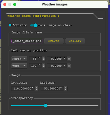
To do this use menu Gribs/Weather images/Open a weather image  and then choose a tab (1 to 8) that looks like this.

In the "File name" field type this link: https://ocean.weather.gov/A_sfc_full_ocean_color.png

and then set the other parameters as shown below.


_____________________________________________________


To do this for the Pacific to look like this:


Choose another tab (2 in this example)

In the "File name" field type this link: https://ocean.weather.gov/P_sfc_full_ocean_color.png

Note the file name is the same except for P for Pacific vs A for Atlantic 

and then set the other parameters as shown below, which are also the same except for the location of the top left corner coordinates.


_____________________________________________________

With one of these images in view, which are vetted by professional human meteorologists, you can over lay a numerical weather model forecast at the same time to evaluate it since it has not been vetted by humans.


In this case we see near perfect agreement that the OPC maps are more and more looking just like the 00h forecast of the GFS, meaning in large part that the GFS is pretty good.  But despite not learning more about the lay of the isobars and hence winds, we do see from the maps where the fronts are located;  fronts are not shown in the GFS model outputs we get in grib format.


Sunday, August 20, 2023

Viewing ASCAT Wind Measurements in OpenCPN

This article outlines the value of ASCAT wind data, and shows how work we have done at Starpath to make these files available on Google Earth can be transcribed to the format needed to be viewed in OpenCPN.  This is effectively a request to OpenCPN developers to automate this conversion process and make the full set of ASCAT data files and then incorporate them into the standard weatherfax plugin.

_______

ASCAT is the name of the scatterometer on two EUMETSAT satellites, Metop-B and Metop-C. They circle the earth in sun-synchronous polar orbits every 1h 41m (101.3m) measuring ocean surface wind speed and direction. They are in the same orbit, but on opposite sides, so they are about 50 min apart, during which the earth rotates 50 min x (15º lon/60 min), or 12.5º of Lon.  Thus the data from C is about 50 min later and  covers a swath of the earth that is 12.5º of Lon farther west—or vice versa, thinking of B following C. We  have extended background on ASCAT at starpath.com/ascat.

These direct wind measurements are the key information needed for weather routing, with a primary use being to evaluate the numerical weather model forecasts. The data are like having thousands of buoys at sea measuring the wind speed and direction, and if a model is to be dependable it should closely match what we see in the buoy measurements.  Also we will periodically see real holes in the wind, or wind shear lines in the ASCAT measurements that are not forecasted in any model. The resolution of the ASCAT data (25 km) is about the same as that of the GFS model (27 km). The expected accuracy of the satellite measurements and that of the model forecasts is about the same, so very roughly ± 2 kts in wind speed and ± 20º in wind direction has to be considered in agreement. 

Remember that the final goal of any numerical weather model is not to reproduce all of the specific observations that went into the computation, but rather to create the best overall forecast at all levels of the atmosphere, which almost always involves some compromise in matching the surface data. Thus, even though the ASCAT measurements are key data assimilated into any global model computation, we should not be surprised that we can learn real and significant discrepancies in the model forecast by looking at the same ASCAT data it was looking at, and when these do disagree, it is the measurements that are of course the correct answer.

ASCAT wind data are available in grib format, but only from two commercial sources, LuckGrib and Expedition, and their data cannot be viewed in other nav programs. This important data, however, are also readily available in graphic format, and OpenCPN is well suite to displaying this data using the powerful WeatherFax plugin—and the process of setting that up is the topic at hand.

We have an important background article on this process Updating Internet File Source for OpenCPN WeatherFax Plugin, which pretty much describes the process in general, but here we need to be more specific on how we generalize the ASCAT data.

We have created two graphic indexes of the files available, one for adjacent US waters the other for adjacent European waters. 


Each of these regions that we have named have four ASCAT files, ascending (satellite moving north, data swaths tilt to the east and descending (satellite moving south, data swaths tilt to the west), one for Metop-B and one for Metop-C.

Here are the 4 examples for what we call the San Francisco region.

San Francisco ASCAT B - Ascending.kml 

San Francisco ASCAT B - Descending.kml

San Francisco ASCAT C - Ascending.kml 

San Francisco ASCAT C - Descending.kml 

You can download anyone or all and drag onto Google Earth (desktop version) to see the latest ASCAT data in that region, defined above. Samples are below (click it, then right-click, open in new tab, and zoom for detailed view).


The times shown in our indexes tell us when new data are expected, which will come in pairs about 50 min apart, with the pairs separated aby about 13 hr.  The times are the valid times of satellite passage, ± 1 hr, but we must wait about 2 hr for the data to be analyzed and made available.  Thus in Biscay, we would expect see new data at about 1230 and 2320 UTC, adding say 30 min to save on air time by asking too early.  Once you have this set up in OpenCPN or Google Earth you will quickly learn how it works. Video examples are listed at starpath.com/ascat.

With that background, we now get to the process of how to convert what we have provided to work with OpenCPN using the weatherfax plugin, which has one of the most convenient displays of graphic weather data of any navigation program.

We have videos on how images are displayed in the weathefax plugin, and as the link above explains OpenCPN stores the data needed for quick display of any image in two files. One provides the link info stating where the data is online and the other specifies the georeferencing coordinate data so the images are displayed in the right place.

The data links are provided in a series of about a dozen XML files called, for example, 

WeatherFaxInternetRetrieval_NAVY.xml, which looks like

<?xml version="1.0" encoding="utf-8" ?>

<OCPNWeatherFaxInternetRetrieval>

  <Server Name="NAVY" Url="https://www.ncei.noaa.gov/jag/navy/data/satellite_analysis/">

      <Region Name="Gulf Stream">

        <!-- Gulf Stream charts -->

        <Map Url="gsncofa.gif" Contents="North Altantic" Area="GS1" />

        <Map Url="gsscofa.gif" Contents="Golf of Mexico" Area="GS2" />

        <Map Url="gsneofa.gif" Contents="Coast Guard North Atlantic" Area="GS3" />

        <Area Name="GS1" lat1="30N" lat2="53N" lon1="80W" lon2="45W" />

        <Area Name="GS2" lat1="17N" lat2="40N" lon1="98W" lon2="65W" />

        <Area Name="GS3" lat1="30N" lat2="60N" lon1="80W" lon2="35W" />

      </Region>

  </Server>

 </OCPNWeatherFaxInternetRetrieval>


These files are located on a PC in:

C:\Users\username\AppData\Local\opencpn\plugins\weatherfax_pi\data


on a Mac, they are located in:

HD\Users\username\Library\Application Support\OpenCPN\Contents\SharedSupport\plugins\weatherfax_pi\data\


We also need to work on the coordinates file which has to include an element for each "server name."

This file is called CoordinateSets.xml  Below we see the section that covers the NAVY server.


   <Coordinate Name="NAVY - Gulf Stream - GS3" X1="304" Y1="60" Lat1="59.00000" Lon1="-76.00000" X2="2122" Y2="1285" Lat2="32.00000" Lon2="-40.00000" Mapping="FixedFlat" InputPoleY="-1515" InputEquator="3031.00000" InputTrueRatio="1.0000" MappingMultiplier="1.0000" MappingRatio="1.0000" />

    <Coordinate Name="NAVY - Gulf Stream - GS1" X1="101" Y1="28" Lat1="53.00000" Lon1="-80.00000" X2="2375" Y2="927" Lat2="32.00000" Lon2="-45.00000" Mapping="FixedFlat" InputPoleY="-2365" InputEquator="3475.00000" InputTrueRatio="1.0000" MappingMultiplier="1.0000" MappingRatio="1.0000" />

    <Coordinate Name="NAVY - Gulf Stream - GS2" X1="376" Y1="82" Lat1="38.00000" Lon1="-94.00000" X2="2236" Y2="746" Lat2="20.00000" Lon2="-67.00000" Mapping="FixedFlat" InputPoleY="-3444" InputEquator="2755.00000" InputTrueRatio="1.0000" MappingMultiplier="1.0000" MappingRatio="1.0000" />


So what we need for OpenCPN is a new set of Retrieval servers and we need new Coordinate Name entries for each of the custom regions we have defined, and these are likely best duplicated, one for Metop-B and one for Metop-C, which makes access to the data a bit easier. 

The new WeatherFaxInternetRetrieval servers would look something like this which covers just two regions. The other 46 would have to be entered into 


<?xml version="1.0" encoding="utf-8" ?>

<OCPNWeatherFaxInternetRetrieval>

<Server Name="ASCAT B" Url="https://manati.star.nesdis.noaa.gov/ascat_images/cur_25km_METB/zooms/">

    <Region Name="Cape Cod ASCAT B">

  <Map Url="WMBas85.png" Contents="Metop-B ascending" Area="85" />

  <Map Url="WMBds85.png" Contents="Metop-B descending" Area="85" />

      <Area Name="85" lat1="38.889N" lat2="51.082N" lon1="75.183W" lon2="59.822W" />

    </Region>

    <Region Name="Bermuda ASCAT B">

      <Map Url="WMBas86.png" Contents="Metop-B ascending" Area="86" />

      <Map Url="WMBds86.png" Contents="Metop-B descending" Area="86" />

      <Area Name="86" lat1="28.9871N" lat2="40.810N" lon1="75.1843W" lon2="59.8349W" />

    </Region>

  </Server>

  <Server Name="ASCAT C" Url="https://manati.star.nesdis.noaa.gov/ascat_images/cur_25km_METC/zooms/">

    <Region Name="Cape Cod ASCAT C">

      <Map Url="WMBas85.png" Contents="Metop-C ascending" Area="85" />

      <Map Url="WMBds85.png" Contents="Metop-C descending" Area="85" />

      <Area Name="85" lat1="38.889N" lat2="51.082N" lon1="75.183W" lon2="59.822W" />

    </Region>

    <Region Name="Bermuda ASCAT C">

      <Map Url="WMBas86.png" Contents="Metop-C ascending" Area="86" />

      <Map Url="WMBds86.png" Contents="Metop-C descending" Area="86" />

      <Area Name="86" lat1="28.9871N" lat2="40.810N" lon1="75.1843W" lon2="59.8349W" />

    </Region>

  </Server>

</OCPNWeatherFaxInternetRetrieval>


and here are the coordinates we need to add to the coordinates file:


<Coordinate Name="ASCAT B - Cape Cod ASCAT B - 85" X1="0" Y1="650" Lat1="38.889" Lon1="-75.183" X2="740" Y2="0" Lat2="51.083" Lon2="-59.822" Mapping="Mercator" MappingMultiplier="1.0000" MappingRatio="1.000" />

<Coordinate Name="ASCAT B - Bermuda ASCAT B - 86" X1="0" Y1="650" Lat1="28.987" Lon1="-75.184" X2="740" Y2="0" Lat2="40.810" Lon2="-59.835" Mapping="Mercator" MappingMultiplier="1.0000" MappingRatio="1.0000" />

<Coordinate Name="ASCAT C - Cape Cod ASCAT C - 85" X1="0" Y1="650" Lat1="38.889" Lon1="-75.183" X2="740" Y2="0" Lat2="51.082" Lon2="-59.822" Mapping="Mercator" MappingMultiplier="1.0000" MappingRatio="1.000" />


<Coordinate Name="ASCAT C - Bermuda ASCAT C - 86" X1="0" Y1="650" Lat1="28.987" Lon1="-75.184" X2="740" Y2="0" Lat2="40.810" Lon2="-59.835" Mapping="Mercator" MappingMultiplier="1.0000" MappingRatio="1.0000" />


The programmer can get these values from the dimensions of our file size, which is always the same at 640 height and 740 width, using the data we provide in our KML files, which in these two cases are: 


<?xml version="1.0" encoding="UTF-8"?>

<kml xmlns="http://www.opengis.net/kml/2.2" xmlns:gx="http://www.google.com/kml/ext/2.2" xmlns:kml="http://www.opengis.net/kml/2.2" xmlns:atom="http://www.w3.org/2005/Atom">

<GroundOverlay>

<name>Bermuda ASCAT B Ascending</name>

<color>7affffff</color>

<Icon>

<href>https://manati.star.nesdis.noaa.gov/ascat_images/cur_25km_METB/zooms/WMBas86.png?</href>

<viewBoundScale>0.75</viewBoundScale>

</Icon>

<LatLonBox>

<north>40.81048097146506</north>

<south>28.98713385708333</south>

<east>-59.83499451605183</east>

<west>-75.184380929696</west>

</LatLonBox>

</GroundOverlay>

</kml>


<?xml version="1.0" encoding="UTF-8"?>

<kml xmlns="http://www.opengis.net/kml/2.2" xmlns:gx="http://www.google.com/kml/ext/2.2" xmlns:kml="http://www.opengis.net/kml/2.2" xmlns:atom="http://www.w3.org/2005/Atom">

<GroundOverlay>

<name>Cape Cod ASCAT B Ascending</name>

<color>7affffff</color>

<Icon>

<href>https://manati.star.nesdis.noaa.gov/ascat_images/cur_25km_METB/zooms/WMBas85.png?</href>

<viewBoundScale>0.75</viewBoundScale>

</Icon>

<LatLonBox>

<north>51.08285287270985</north>

<south>38.88930541210142</south>

<east>-59.82222792454112</east>

<west>-75.18387376026712</west>

<rotation>-0.5009419918060303</rotation>

</LatLonBox>

</GroundOverlay>

</kml>


Note that ascending and descending for both B and C are the same dimensions, although the files have different, systematic names. The file number changes, here 85 vs 86, and the term METB changes to METC, plus the ascending vs descending changes from WMBas85 to WMBds85.


Here is what we see when we append the new ASCAT servers into the NAVY retrieval file and also append into the stock coordinates file the four listed above:


Viewing ASCAT winds in OpenCPN


My guess is that one of the talented developers that contribute to OpenCPN could download all 48 of our ASCAT regions and then write custom code to open each one and generate the right retrieval and coordinate statements to make it work for all of this data.  I also guess that this would not take too long. We have spent a large amount of time  in creating what we have, with the hopes that the rest will go very fast.


In the meantime, if someone could benefit from this data before that happens, the process can be created manually as we have done here.